CFD optimization of an Oscillating Water Column
Wave Energy Converter (OWC)
Year
2021
Institution
NIT Surat
Publication
Springer Lecture Notes in Mechanical Engineering, 2022
Tech & tools
- ANSYS Fluent
- CFD
- VoF Multiphase
- SST k-ω
- Stokes 5th-order
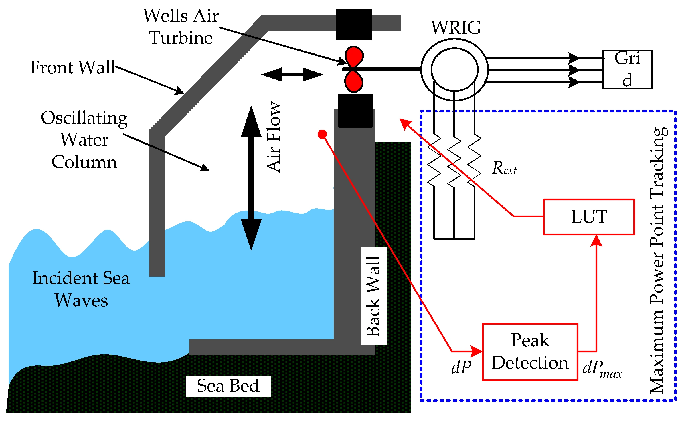
The Oscillating Water Column (OWC) is a renewable-energy device that uses the motion of ocean waves on a partially-submerged chamber to compress and decompress an air column, driving a power-take-off (PTO) turbine at the chamber vent. Efficiency is governed by chamber pressure, free-surface velocity, and free-surface elevation. This research validated an OWC numerical model against published experiments and proposed two design modifications that significantly improved hydrodynamic efficiency.
Numerical approach. Built a 2-D Numerical Wave Tank (NWT) in ANSYS Fluent using the Homogeneous Volume-of-Fluid multiphase model with an implicit scheme (global Courant ~0.1). The Navier–Stokes equations were solved alongside a transport equation; turbulence was modeled with SST k-ω.
Solver setup:
- Gradient: Green Gauss cell-based
- Pressure: body-force weighted
- Momentum: 2nd-order upwind
- Volume fraction: compressive
- Turbulence: 2nd-order upwind
Wave generation. Used Fluent’s integrated open-channel-flow and open-channel-wave boundary conditions as part of the VoF sub-models. The inlet velocity boundary applied Stokes 5th-order wave theory to generate shallow / intermediate waves with the following parameters:
- Wavelength λ: 4.07 m
- Time period T: 1.7019 s
- Water depth h: 0.92 m
- Wave height H: 0.12 m
Hydrodynamic efficiency. The OWC chamber’s hydrodynamic efficiency determines how much power is available at the vent. Inside the chamber, the free surface rises with incident wave energy, generating pressure that drives air through the vent. Output power is estimated from the free-surface oscillating motion:
- Incident wave power:
Pi = (1/8 ρg H²) × (ω/k) × [1/2 (1 + 2kh/sinh(2kh))] - Hydrodynamic power:
Phyd = p × A × u(p = pressure, A = chamber area, u = free-surface velocity) - Efficiency:
ε = Phyd × 100 / Pi
Validation model. Built the NWT to match the experimental setup of Morris-Thomas et al. — chamber located 37.5 m from the wave-generation zone, NWT height 2.2 m, chamber height 1.275 m, front-wall draught 0.15 m, chamber length 0.64 m. Vent size 0.05 m, with porous-media damping applied through that vent to simulate the PTO. Porous-media permeability was tuned via Darcy’s law to match experimental damping behavior — C = 1/kp was calculated as 3.6 × 10⁸ for the given porous-media length. Meshing was handled in GAMBIT, with 0.01 m elements near the free surface and chamber front wall and 0.025 m elements elsewhere.
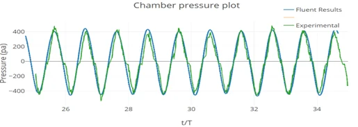
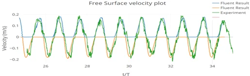
The numerical outputs were in close agreement with experiment. Incident power was calculated as ~38.34 W; baseline peak and average efficiencies were 66.5% and 28.8% respectively.
Design modifications. Two modifications were proposed, both targeting the chamber geometry while keeping all other parameters constant.
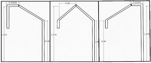
Modification 1 — chamber shape and vent location. Repositioned the vent across three locations (left, middle, right) and gave the previously-horizontal supporting walls specific slopes. The intent was to improve pressure-to-velocity conversion at the vent, drawing on the efficiency differential between orifice-meters and nozzle-meters.
Modification 2 — vertical plates. Added four equally-spaced vertical plates (thickness 0.02 m, height 0.22 m, spacing 0.1122 m) inside the chamber. Per Masoomi et al., interior plates enforce a more uniform piston-type oscillation, significantly raising efficiency.
Results. Efficiency improvements across the modified configurations:
| Configuration | Peak Efficiency (%) | Average Efficiency (%) |
|---|---|---|
| Baseline | 66.50 | 28.80 |
| Mod 1 – Left Vent | 76.76 | 34.04 |
| Mod 1 – Mid Vent | 75.02 | 27.35 |
| Mod 1 – Right Vent | 74.64 | 34.44 |
| Mod 2 – Left Vent | 87.82 | 40.75 |
| Mod 2 – Mid Vent | 90.27 | 34.03 |
| Mod 2 – Right Vent | 86.85 | 37.87 |
The best configuration (Mod 2 – Mid Vent) reached 90.27% peak efficiency. Mod 2 – Left Vent gave the highest average efficiency at 40.75%. Both modifications meaningfully improved energy capture across the wave cycle.
Publication. Published in Springer Lecture Notes in Mechanical Engineering, 2022. The work contributes both a numerical validation methodology and a set of practical geometric modifications for OWC chamber design.